| |
 Click to Enlarge
|
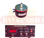
Pressure to Current Trainer
This setup comprises of pressure chamber fitted on a base board. A pressure transducer and bourdon pressure gauge are fitted to the chamber. Digital pressure indicator with transmitter output 4 to 20 mA can be measured by a current meter. Foot air pump is provided to build the pressure. Specification: Pressure sensor : Strain gauge based pressure transducer
Capacity : 30 PSI
Pressure Source : Foot air pump
Indicator : 3? digit LED display
Output : 4 - 20 mA
Power : 230 V 50 Hz
See Enlarge
|
|
|
|
 Click to Enlarge
|
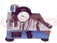
Vibration Measurement Trainer
This comprises of vibration generator of capacity 5 Newton with vibration exciter. Piezoelectric accelerometer is used to sense the vibration. Digital display unit will display displacement, Velocity & acceleration sensed by the sensor. Specification: Vibration Generation : Capacity 5 Newton
Excitation Frequency : 50 Hz to 1 K Hz
Excitation Voltage : 0 to 10 V P to P
Vibration Sensor : Piezoelectric type accelerator
Vibration Indicator : 3? digit LCD display by selection through selector switch
Range : Acceleration - 0.1 to 199.9 m/s?
Velocity - 0.001 to 19.99 cm/s rms)
Displacement - 0.003 to 1.999 mm (p-p)
Power : 230 V 50 Hz
See Enlarge
|
|
|
|
 Click to Enlarge
|
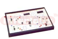
Dead Weight Pressure Gauge Tester
This is ideal for testing and calibration of pressure gauges, pressure transducers, recorders, digital calibrators etc..The system used in the dead weight is vertically mounted precision lapped piston and cylinder assembly with accurately calibrated mass for loading the piston. Pressure is build easily by single cylinder pump at very high rate. The whole system is housed inside a stainless steel case with elegant look. Pressure ports are provided to fix the gauges to be tested. Acrylic see through oil tank is designed to use it as oil reservoir. Specification: Capacity : 1 to 10, 1 to 25, 1 to 50, 1 to 100, 1 to 200
Pressure port : 3/8 BSP thread
Accuracy : 0.1% of FSD
Starting Pressure : 0.5 Kg/cm?
Size : 350x350x200 mm(LxBxH)
See Enlarge
|
|
|
|
 Click to Enlarge
|
Bourdon Guage Trainer
This comprises of bourdon pressure gauge fitted on a pressure chamber, a displacement sensor is attached to the edge of the bourdon tube to sense the deflection of the bourdon tube due to pressure. The displacement indicator is provided to measure the deflection of the tube in terms of pressure and also in mm. Specification: Sensor : LVDT of ?2.5mm fitted to the edge of bourdon tube.
Master Gauge : Bourdon tube pressure gauge
Display : 3? digit to read pressure upto 30 PSI and displacement upto ?2.5mm
Pressure Source : Foot pump to build pressure upto 30 PSI
See Enlarge
|
|
|
|
 Click to Enlarge
|
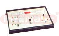
Instrumentation Tutor
This comprises of temperature and speed using different methods. RTD, thermistor and thermocouple are used as sensors with digital temperature indicator to measure temperature. A small water kettle is supplied as a temperature source upto 100?C. Glass bead thermometer is used as standard temperature measurement source to conduct the experiment. Magnetic and photo reflective sensors are used to measure speed. A FHP motor with speed regulator is used as speed source. To the shaft 60 teeth tone wheels are fixed to generate pulses.
See Enlarge
|
|
|
|
 Click to Enlarge
|
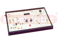
Instrumentation Tutor II
This comprises of measurement of displacement & strain. To measure the displacement, LVDT is used as sensor of range ? 10 mm. A calibration jig with micrometer is supplied to conduct the experiment. For strain measurement cantilever beam bonded with four strain gauges is used as sensor. Pan and weights up to 1kg is provided to conduct the experiment. Digital readout is provided to measure the parameters.
See Enlarge
|
|
|
|
 Click to Enlarge
|
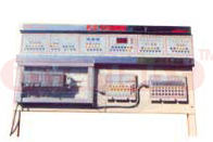
Instrumentation Tutor III
This comprises of piezoelectric crystal to measure vibration force, LDR to measure light intensity with respect to distance, capacitance to measure displacement, resistance to measure angular displacement and inductance also to measure displacement. The components used are supplied with the setup to conduct the experiments. An attempt is made to demonstrate the usage of the components in measurement and instrumentation field. Digital readout is provided to show the measured parameter.
See Enlarge
|
|
|
|
 Click to Enlarge
|
Instrumentation Tutor IV
This is ideal for testing and calibration of pressure gauges, pressure transducers, recorders, digital calibrators etc..The system used in the dead weight is vertically mounted precision lapped piston and cylinder assembly with accurately calibrated mass for loading the piston. Pressure is build easily by single cylinder pump at very high rate. The whole system is housed inside a stainless steel case with elegant look. Pressure ports are provided to fix the gauges to be tested. Acrylic see through oil tank is designed to use it as oil reservoir. Specification: Capacity : 1 to 10, 1 to 25, 1 to 50, 1 to 100, 1 to 200
Pressure port : 3/8 BSP thread
Accuracy : 0.1% of FSD
Starting Pressure : 0.5 Kg/cm?
Size : 350x350x200 mm(LxBxH)
See Enlarge
|
|
|
|
 Click to Enlarge
|
PLC Trainer
Main Unit Specification
Micro Processor based PLC system with built in 12 Digital Input, 8 Digital Output line, 4 Analog Input & 1 Analog Output and RS 232 serial interface to up load and down load facility to / from PC system with required software compactable with IBM PC to facilitate to use Ladder Editor Programs. Static Application Program:
Common Base Board for static Application Panel (8 LEDS with 10 LED bar graph for AO & 32 sockets) with replaceable application Panels as listed below. 1. Door Bell Operation
2. Switching of Lights
3. Silo Control
4. 7Segment display
5. Starter Control
6. Sequential control of motor
7. Star delta Control
8. Resistance welding
9. Tank level Control
10. Traffic Light Control
11. Bottling Plant
12. Drink Dispenses
13. Reaction Vessel
14. Oven
15. Parking garage
16. Combination Lock
17. Elevator Simulator
18. Process Control Trainer
19. Washing Machine
20. Steppen Motor
21. Speed Control Distributor Panel
For Easy connection of input/out of PLC to the field/static application through use of patch cords
1. For Digital Input & Output: consist of 12 Digital inputs and 8 Digital output
4mm socket for Digital Input : 24 Nos
4mm socket for Digital Input: 16 Nos
2. For Analog Input & output: consist of 4 Analog Input & 2Analog output
4mm socket for Analog Input: 8 Nos
4mm socket for Analog Output: 4 Nos Simulation + Extension Panel
For simulation of digital/Analog I/Os & extension for inputs and outputs for connecting same I/P or O/P at different points. 1. For digital I/P consists of Toggle switches: 8 Nos., pushbuttons: 4 Nos, 4mm Socket: 24 Nos.
2. For Digital output consists of 24 VDC LED lamps: 8 Nos.
3. For analog I/P 4ch. Consist of 4 Nos. of Potentiometers (for varying Analog Voltage) 0 to +10
4. For Analog output 2 ch.4-20 mA to voltage converter for AO ICH 4mm sockets: 4 Nos. Salient Features
Front-end connection through 4mm sockets and patch cards or fixed I/O connection with Toggles switches and L.E.Ds.
Simulation and extension through switches and pots
Various Static application dependent programs to be interfaced with PLC.
Learning and Troubleshooting Skills through front panel.
Study of Ladder Diagram
Dynamic Ladder Diagram
Dynamic Ladder display on personal computer.
Light weight study panel
Sufficient Courseware: Literature for Various Static application dependent programs Instructor's Guide, Technical Reference. Specification of PLC Make : ALLEN BRADLY/ ABB Or Equivalent Make
DI : 12 Built in
Do : 8 Built in
AI : 4 Built in
AO :1 Built in
PC Interface : RS 232 Cable
See Enlarge
|
|
|
|
 Click to Enlarge
|
Tool Dynamometer & Indicators
Used for measuring cutting forces on various machines like lathe, drill, milling machines. All three direction forces are measured simultaneously and displayed. Tool dynamometers are useful to study, analyze the optimum feed, speed and depth of cut on different materials. The dynamometers are also available in various capacities as per customer requirement
See Enlarge
|
|
|
|
 Click to Enlarge
|
Differential Pressure Transmitter Trainer
This table top model comprises of two pressure chambers. One for high pressure and another for low pressure gauges. The differential pressure transmitter is connected to the two chambers. The pressure is built by a foot air pump. Digital instrument is provided to indicate the differential pressure with transmitter output. Specification: Sensor : Strain gauge based differential pressure sensor
Capacity : 30 PSI
Pressure Sensor : Bourdon tube pressure gauges
Pressure Source : Foot air pump
Display : 3? digit LED display indicator
Output : 4-20mA output
Power : 230 V 50 Hz supply
See Enlarge
|
|
|
|
 Click to Enlarge
|
Level Control Setup
Level Control Setup comprises of Measuring tank fitted with Level transmitter to measure the Water Level. The Flow of water is controlled by a control valve actuated by a I to P converter. Rotameter is provided to measure the flow rate. The system is mounted on a table top model with all necessary pipings. The water inlet and outlet is provided through a manual control valve. Water at approx. 100 LPH has to be supplied to the system externally. The electronic panel comprises of ADC/DAC card with RS-232 interface. Displays indicate the process value and set value. Software is provided for experimentation, PID Control settings (P, PI, PD and PID mode) Data storing, Online data acquisition, Off line analysis, Printing of data's can be done easily. Specification :
Level Sensor : Capacitance Type Level Sensor.
Output : 4 - 20m A
Measuring Tank: Capacity 5 liters, with graduation.
Rotameter : 10-100 LPH
Control Value :Globe 2 way ?" with Diaphragm type actuator, Total stem travel 18mm, Air operated, 3 to 15 PSI pressure.
Air Regulator : ?" BSP, for 1 to 15 PSI pressure
I/P Converter :4 to 20mA input output 3 to 15 PSI
ADC/DAC Card : 12 bit resolution, 8 input 1 output with RS 232 Serial Interface to PC.
PID Controller :Software to set P, PI, PID, PD Mode with Controller and Data Acquisition, Trend plot, Offline, Analysis and Printing.
See Enlarge
|
|
|
|
 Click to Enlarge
|
Temperature Control Setup
Temperature Control Loop Setup comprises of RTD temperature Sensor to sense the temperature. The water glows through the Rotameter and Process tank to which a heating coil is fitted. The heater is controlled by a Thyrister drive. The Thyrister drive is connected to PID controller. The manual control valve can control the water flow. The system is mounted on a tabletop model with all necessary piping. The water inlet and outlet are brought out through a manual control valve. Water at approx. 100 LPH has to be supplied to the system externally.The electronic panel comprises of ADC/DAC card with RS-232 interface. Displays indicate the process value and set value. Software is provided for experimentation, PID Control settings (P, PI, PD and PID mode) Data storing, Online data acquisition, Off line analysis, Printing of data's can be done easily. Specification : Temperature transmitter : RTP (PT-100) with transmitter Output 4 - 20m A
Rotameter: 10-100 LPH
Heater : 1.5 KW
Thyrister : 1.5KW with 4 to 20 mA input to control heater.
ADC/DAC Card :12 bit resolution,8 input 1 output with Rs 232 Serial Interface to PC.
PID Controller: Software to set P, PI, PID, PD Mode with Controller and Acquisition, Trend plot, Offline, Analysis and Printing.
See Enlarge
|
|
|
|
 Click to Enlarge
|
Pressure Control Setup
Pressure Control Setup comprises of Pressure tank fitted with Pressure transmitter to measure the pressure. The pressure is controlled by a pneumatic control valve operated by a I to P converter. The input pressure is fed from air compressor. The whole system is mounted on a Table top Model with all necessary Piping.
The electronic panel comprises of ADC/DAC card with RS-232 interface. Displays indicate the process value and set value.
Software is provided for experimentation, PID Control settings (P, PI, PD and PID mode) Data storing, Online data acquisition, Off line analysis, Printing of data's can be done easily. Specification :
Pressure Transmitter: 5 Kg/cm2 strain gauge based.
Output : 4 - 20m A
Pressure Tank : 2 Liter Capacity
Control Value : Globe 2 way ?" with Diaphragm type actuator, Total stem travel 18mm, Air operated, 3 to 15 PSI pressure.
Air Regulator : ?" BSP, for 0 to 15 PSI pressure
I/P Converter : 4 to 20mA input output 3 to 15 PSI
ADC/DAC Card : 12 bit resolution,8 input 1 output with Rs 232 Serial Interface to PC.
PID Controller : Software to set P, PI, PID, PD Mode with Controller and Acquisition, Trend plot, Offline, Analysis and Printing.
See Enlarge
|
|
|
|
 Click to Enlarge
|
Temperature Controller cum Indicator
Each powder coated panel comes with each type of sensors and Temperature which will enable the student to segregate and do the practicals more effectively and efficiently by finding out the mill volt and checking the corresponding Temperature in C with the help BSIS charts. 1. 'J' Type
2. 'K' type
3. RTD Type/PT 100
See Enlarge
|
|
|
|
|


